Finned Heaters for Efficient Air & Gas Heating
High-efficiency electric finned heaters designed for forced airflow applications, delivering enhanced heat transfer, reduced sheath temperature, and long service life in industrial environments.

Finned Heater Product Configurations
Explore Our Range of Efficient, Customizable Heaters for Every Industrial Application
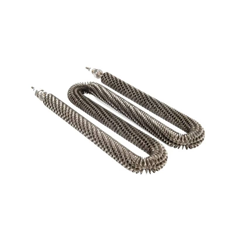
U-Shaped Finned Heater
Compact heater for duct and enclosure airflow
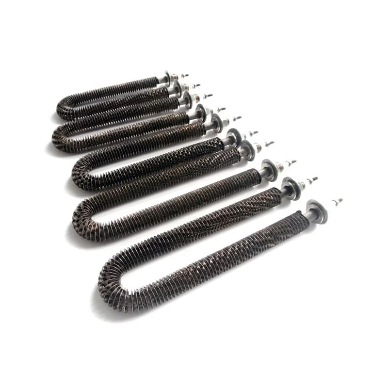
M-Shape Finned Tubular Heater
Extended heating coverage in confined layouts
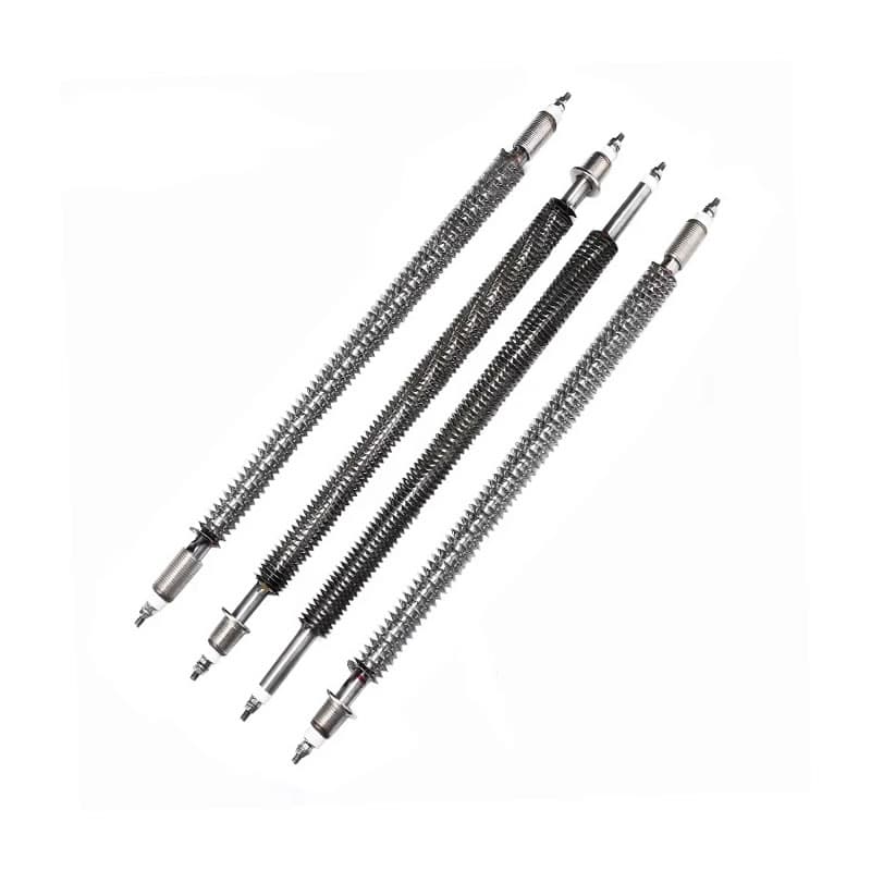
Straight-Tube Finned Heater
Standard configuration for general air heating
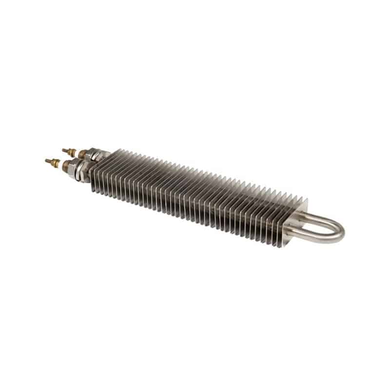
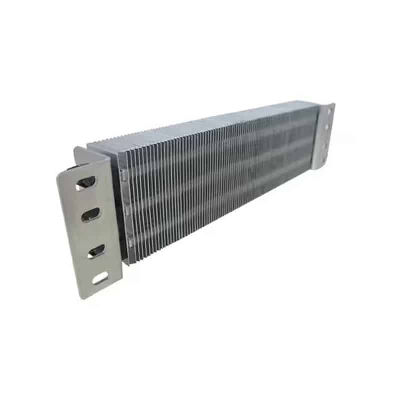
Finned Strip Heater
Flat-profile heater for surface and air heating
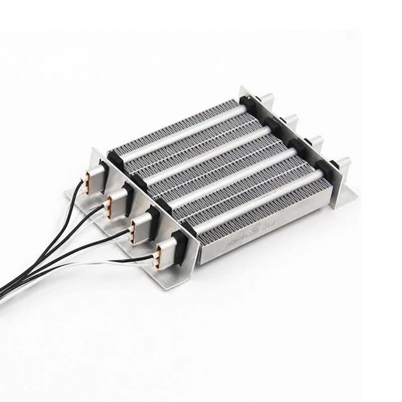
High-Power Finned Heater
Heavy-duty solution for high-capacity systems
Custom Formed Finned Heater
Custom-shaped finned heating solutions
Families
- Finned Tubular Heater — Straight or formed; single- or double-ended;
- Finned Strip Heater — 0.375″ thickness class; bolt-on;
- Finned Cartridge Heater — Select for localized air heat;
Applications
- Make-up air & process ovens, drying tunnels.
- Cabinet/enclosure heating; dehumidification.
- HVAC reheat & test chambers .
Performance
- Typical W/in²: 40–60 (air)
- Fin pitch: 4.5–6 (up to 8)/in
- Lengths up to 120″
Applications of Finned Heaters
Designed for efficient air heating across diverse industrial and commercial environments

HVAC & Air Handling Systems
High-efficiency air heating for ducts, AHUs, and ventilation systems.

Load Banks & Power Testing
Reliable heat dissipation for generator, UPS, and battery testing systems.

Industrial Ovens & Drying Equipment
Uniform heating for curing, drying, and thermal processing applications.

Control Cabinets & Dehumidification
Prevent condensation and maintain stable temperatures in electrical enclosures.
Why Choose DarwinHeat
Maximized Efficiency, Durability, and System Compatibility

Thermal Headroom
Optimized fin pitch and mechanically bonded or furnace-brazed fins for maximum heat transfer efficiency and lower sheath temperature.

Materials for duty
Steel for clean, dry air; 304/316L stainless steel for humid or corrosive environments; high-nickel Incoloy® for high-temperature oxidation resistance.

Forming & Mounting
Precision bending (minimum radii based on tube diameter) with bulkhead fittings, collars, locator washers, and mounting brackets for easy installation.

Electrical Integrity
High dielectric strength, megger-tested, moisture-sealed terminals; optional hermetic feed-throughs ensure safe operation in harsh conditions.

System Integration
Supports banked arrays, terminal boxes, and safety interlocks such as airflow sensors, high-limit thermostats, and SSR/thyristor control for seamless system compatibility.

Documentation & Support
Comprehensive 2D/3D CAD files, watt density guidelines, airflow sizing worksheets, and certification files for engineering and installation support.
General Specifications
| Parameter | Specification | Notes |
| Voltage Range | 12V – 600V | Customizable (Single/3-Phase) |
| Wattage Tolerance | +5%, -10% | Standard IEC/NEMA tolerance |
| Resistance Tolerance | ±10% | Cold state |
| Insulation Resistance | ≥ 500 MΩ | @ 500V DC (Cold state) |
| Leakage Current | ≤ 0.5 mA | @ Rated Voltage (Cold state) |
| Dielectric Strength | 1500V / 1 min | No breakdown / No flashover |
| Frequency | 50Hz / 60Hz | Universal compatible |
| Surface Load | Max 6 – 8 W/cm² | Dependent on air velocity* |
Engineer’s Note: Recommended surface load depends on air speed. For still air, recommend < 4 W/cm². For moving air > 6 m/s, the power density can reach up to 8 W/cm².
Standard Dimensional Data
| Tube Diameter | Fin Outer Diameter | Fin Width | Fin Pitch | Max Length |
| Ø 8.0 mm | Ø 18.0 mm | 5.0 mm | 3 – 5 mm | 6000 mm |
| Ø 10.0 mm | Ø 20.0 mm | 5.0 mm | 3 – 5 mm | 6000 mm |
| Ø 11.0 mm | Ø 21.0 mm | 5.0 mm | 3 – 5 mm | 6000 mm |
| Ø 12.0 mm | Ø 22.0 mm | 5.0 mm | 3 – 5 mm | 6000 mm |
| Ø 16.0 mm | Ø 26.0 mm | 5.0 mm | 4 – 6 mm | 6000 mm |
This table addresses the question of whether it will fit. We need to define the specific dimensions of the pipe diameter and fins.
Material Selection Guide
| Material Grade | Max Sheath Temp | Typical Application Environment |
| Carbon Steel | 400°C (750°F) | Oil heating, Non-corrosive gas, Low cost applications. |
| SUS 304 | 650°C (1200°F) | General air heating, Food industry, HVAC systems. |
| SUS 316L | 650°C (1200°F) | Humid environments, Marine, Mild chemical corrosion. |
| Incoloy 840 | 760°C (1400°F) | High temp oxidation resistance, Superior durability. |
| Incoloy 800 | 870°C (1600°F) | Extreme high temp, high-watt-density |
Finned Heater Manufacturing Process
Our precision manufacturing process ensures every finned heater delivers reliable performance and extended service life under real working conditions.

Element build
Nickel‑chromium resistance coil centered in a metal sheath; compacted with high‑purity MgO for thermal conduction and dielectric strength.

Finned
Helical metal fins wound onto the sheath; bonding via furnace brazing for steel fins (or mechanical wrap for SS/Monel); selected fin pitch (typically 4.5–6 fins/in).

Forming
Anneal and bend to geometry; maintain minimum bending radii by diameter to protect MgO pack.

Terminations & seals
Studs, quick-connects, lead terminations with ceramic/mica insulators; moisture seals (RTV, epoxy, glass-ceramic); optional hermetic terminals.

Surface treatment
High‑heat aluminum coating, high‑emissivity black, nickel plate, or bright‑annealed finish; optional passivation for stainless.

Quality assurance
Resistance & tolerance check, hipot and insulation resistance, visual fin bond inspection, sheath straightness/runout, marking & serialization.
The key questions that need to be answered before selecting a Finned heater are
Contact our engineers with your detailed operating conditions for precise sizing and material recommendations.
Request a Quote or Engineering Support
Get fast, application-specific recommendations and pricing from our heating engineers.