Why Airflow Velocity Is the Deciding Factor in Finned Heating Element Efficiency
In forced-convection thermal systems, the performance of a finned tubular heater is not a static metric. While the electrical wattage remains constant, the heater’s ability to dissipate that energy is entirely dependent on the fluid dynamics of the surrounding air. For engineers designing duct heaters or industrial ovens, understanding the non-linear relationship between airflow and sheath temperature is critical to preventing premature element failure.

Convective Coefficients and the Breakdown of the Thermal Boundary Layer
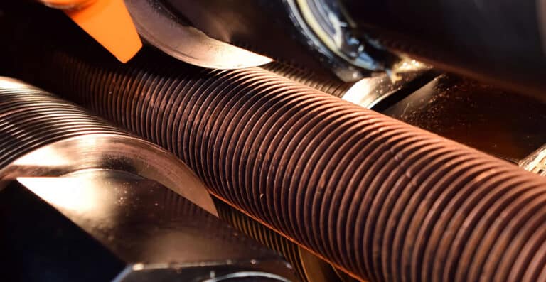
The primary advantage of adding fins to a tubular heater is the massive increase in surface area, but this area is only effective if the airflow can strip away the “stagnant” air layer. At low velocities, air tends to move in a laminar flow pattern, creating a thick thermal boundary layer that acts as an insulator around the fins.
As airflow velocity increases, the flow transitions to a turbulent state. This turbulence breaks down the boundary layer, significantly increasing the convective heat transfer coefficient ($h$). In practical terms, increasing airflow doesn’t just improve cooling linearly; it exponentially improves the heat transfer efficiency. This allows the element to operate at a much lower internal temperature while delivering the target $BTU$ output to the process.
Managing the Critical Threshold of Sheath Temperature
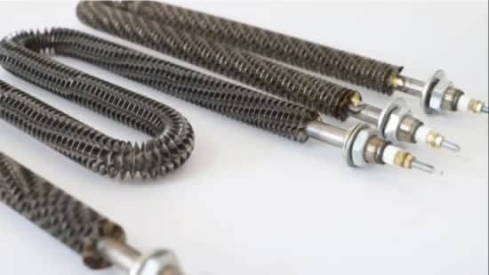
Every finned heater has a maximum allowable sheath temperature, typically dictated by the grade of stainless steel or Incoloy used. If the airflow drops below a specific Linear Feet per Minute (LFM) threshold, the heat generated by the resistance wire begins to “stack” within the magnesium oxide (MgO) insulation.
- High-Velocity Environments: Allow for higher watt densities (up to $50\text{–}60\text{ W/in}^2$) because the high-speed air rapidly carries away the thermal energy.
- Low-Velocity/Stagnant Environments: Require a drastic reduction in watt density ($20\text{–}25\text{ W/in}^2$) to prevent the fins from glowing red, which leads to rapid oxidation and catastrophic sheath failure.

How Fin Density and Airflow Uniformity Affect System Pressure Drop
A common design conflict in OEM equipment is the balance between heat transfer and pressure drop. While high-density fins (e.g., 8 to 10 fins per inch) provide more surface area for heat exchange, they also create significant back-pressure for the blower system.
If the blower cannot overcome this resistance, the air will bypass the heater through the paths of least resistance—usually the gaps between the heater frame and the duct wall. This results in “hot spots” where certain sections of the element are starved of air. Achieving a uniform velocity profile across the entire face of the heater bank is essential to ensure that no single element exceeds its thermal design limit.
The Impact of Air Density on Cooling Efficacy in High Temperature Loops
It is a common engineering oversight to ignore the temperature of the incoming air. As air temperature rises, its density decreases, which in turn reduces its mass flow rate and its ability to absorb heat.
When designing recirculating ovens where the inlet air may already be at $200^\circ\text{C}$, the airflow velocity must be significantly higher than in a “fresh air” intake system. Failure to account for this reduced density often leads to mysterious heater burnouts in high-temperature process loops, even when fan speeds appear adequate on paper.
Optimize Your Thermal System with DarwinHeat
Understanding the intersection of fluid dynamics and electrical heating is what separates a standard installation from a high-performance system. At DarwinHeat, our engineers utilize airflow modeling to help you select the ideal fin pitch, wattage, and material for your specific duct geometry.